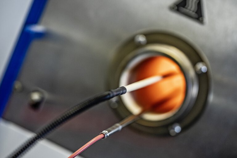
Thermocouples are indispensable in industrial processes and are suitable for wide temperature ranges. They are available as different types and are mostly used at high temperatures or in industrial furnaces. Learn more about the heat resistant temperature sensor!
Thermocouples are based on the principle of comparative measurement and consist of two metallic conductors of different materials that are welded together at the tip. Depending on the material pairing, they have different levels of thermoelectric voltage and are suitable for different temperature ranges. The most commonly used are thermocouples type K and thermocouples type J.
Normally, the thermocouple consists of a combination of two materials with diameters ranging from 0.2 to 5 mm. When using noble materials such as rhodium or platinum, these dimensions range from 0.1 to 0.5 mm. When selecting a thermocouple material, care should be taken to ensure that it has a high Seebeck factor and that temperature affects its value as little as possible in order to achieve a linear characteristic. The appropriate thermocouple material is selected according to the range of the measured temperature.
The probe's casing is exposed to very high temperatures, so it is necessary to use different types of steel. At the highest temperatures, the thermocouple protection tube is made of heat-resistant steel or ceramic materials. The thermowell must be resistant to corrosion, thermal shock and mechanical damage. A desirable feature to prevent corrosion of the thermocouple is the impermeability of gases that could significantly accelerate the aging process of the thermocouple. There are also designs without a cover that are used to reduce dynamic errors. For special measurements, such as the temperature of liquid metals, glass or liquid steel, highly specialized thermocouple designs are used.
The thermowell must be resistant to corrosion, thermal shock and mechanical damage. A desirable feature to prevent corrosion of the thermocouple is the impermeability of gases that could significantly accelerate the aging process of the thermocouple. Designs without a cover can be used to reduce dynamic errors.
Also, when selecting a thermocouple material, care should be taken to ensure that it has a high Seebeck factor and that temperature affects its value as little as possible to achieve a linear characteristic.
In contrast to a resistance thermometer, a thermocouple can be used in a much higher temperature range. In addition, thermocouples are more robust and resistant to mechanical stress.
Unter der Vielzahl möglicher Metallkombinationen wurden bestimmte ausgewählt und in ihren Eigenschaften genormt, insbesondere der Spannungsreihe und den zulässigen Grenzabweichungen. Die folgenden Elemente sind hinsichtlich der Thermospannung und deren Toleranz sowohl weltweit (IEC) genormt als auch europäisch bzw. national genormt.
Farbkennzeichnung bei Thermoelementen
|
Element |
Maximaltemperatur |
Definiert bis |
Plusschenkel |
Minusschenkel |
|
|
Fe-CuNi |
„J“ |
750°C |
1200°C |
schwarz |
weiß |
|
Ce-CuNi |
„T“ |
350°C |
400°C |
braun |
weiß |
|
NiCr-Ni |
„K“ |
1200°C |
1370°C |
grün |
weiß |
|
NiCr-CuNi |
„E“ |
900°C |
1000°C |
violett |
weiß |
|
NiCrSi-NiSi |
„N“ |
1200°C |
1300°C |
rosa |
weiß |
|
Pt10Rh-Pt |
„S“ |
1600°C |
1540°C |
orange |
weiß |
|
Pt13Rh-Pt |
„R“ |
1600°C |
1760°C |
orange |
weiß |
|
Pt30Rh-Pt6Rh |
„B“ |
1700°C |
1820°C |
grau |
weiß |
|
Thermoelemente nach DIN EN 60 584 |
|||||
|
Element |
Maximaltemperatur |
Definiert bis |
Plusschenkel |
Minusschenkel |
|
|
Fe-CuNi |
„L“ |
700°C |
900°C |
rot |
blau |
|
Ce-CuNi |
„U“ |
400°C |
600°C |
rot |
braun |
|
Thermoelemente nach DIN 43 710 |
|||||
Farbkennzeichnungen für Thermoelemente nach
|
Element |
Typ |
Mantel |
Plusschenkel |
Minusschenkel |
|
Cu-CuNi |
„T“ |
braun |
braun |
weiß |
|
Fe-CuNi |
„J“ |
schwarz |
schwarz |
weiß |
|
NiCr-Ni |
„K“ |
grün |
grün |
weiß |
|
NiCrSi-NiSi |
„N“ |
rosa |
rosa |
weiß |
|
NiCr-CuNi |
„E“ |
violett |
violett |
weiß |
|
Pt10Rh-Pt |
„S“ |
orange |
orange |
weiß |
|
Pt13Rh-Pt |
„R“ |
orange |
orange |
weiß |
|
Farbkennzeichnungen für Thermoelemente nach DIN EN 60 584 |
||||
|
Element |
Typ |
Mantel |
Plusschenkel |
Minusschenkel |
|
Fe-CuNi |
„L“ |
blau |
rot |
blau |
|
Ce-CuNi |
„U“ |
braun |
rot |
braun |
|
Farbkennzeichnungen für Thermoelemente nach DIN 43 713 |
||||
|
Element |
Typ |
Mantel |
Plusschenkel |
Minusschenkel |
|
NiCr-Ni |
„K“ |
grün |
rot |
grün |
|
Pt10Rh-Pt |
„S“ |
weiß |
rot |
weiß |
|
Pt13Rh-Pt |
„R“ |
weiß |
rot |
weiß |
|
Farbkennzeichnungen für Thermoelemente nach DIN 43 714, Status 1979 |
||||

Voltages of different thermocouples relative to a reference temperature of 0 °C according to DIN EN 60584
The principle of thermocouples is the result of the so-called Seebeck effect. This phenomenon can be explained by the theory of free electrons, according to which different types of conductors have a different density of free electrons. At the contact point of two different conductors forming a thermocouple, electrons will move from one conductor to the other. A larger number of electrons will move from a higher density conductor to a lower density conductor. The intensity of electron migration depends on the temperature of the contact point of the two conductors, it is also higher the higher the temperature. The electromotive force formed in a thermocouple circuit consisting of two different conductors whose ends have been placed at different temperatures is given by the formula:
V=(S-SA)⋅(T2-T1)
The resulting electromotive force is on the order of a few to several dozen microvolts per degree Celsius.
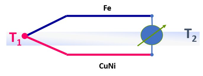
Example measuring chain thermocouple
Die Auswahl des Thermoelement-Typs hängt in erster Linie von der Einsatztemperatur ab. Weiterhin sollte ein Element mit hoher Thermospannung gewählt werden, um ein möglichst störunempfindliches Messsignal zu erhalten. In der folgenden Tabelle sind die verschiedenen Elemente zusammen mit einer kurzen Charakterisierung aufgeführt. Die empfohlenen Maximaltemperaturen können nur als Eckwerte angenommen werden, da sie stark von den Einsatzbedingungen abhängen. Sie beziehen sich auf einen Drahtdurchmesser von 3 mm bei den unedlen und 0,5 mm bei den edlen Elementen.
|
Cu-CuNi |
350°C |
Geringe Verbreitung. |
|
Fe-CuNi |
700°C |
Stark verbreitet, preiswert, korrosionsgefährdet. |
|
NiCr-CuNi |
700°C |
Geringe Verbreitung, hohe Thermospannung. |
|
NiCr-Ni |
1000°C |
Im Bereich von 800 - 1000°C oft eingesetzt, auch für den unteren Temperaturbereich geeignet. |
|
NiCrSi-NiSi |
1300°C |
(Noch) wenig verbreitet. Kann teilweise edle Elemente ersetzen. |
|
Pt10Rh-Pt |
1500°C (1300°C) |
Hohe Kosten, sehr gute Langzeitkonstanz, eng toleriert. |
|
Pt30Rh-Pt6Rh |
1700°C |
Hohe Kosten, geringste Thermospannung, hohe Maximaltemperatur. |
The length of the thermocouple or compensation cable is of secondary importance due to the low internal resistance. However, for longer cable lengths with a small cross-section, the resistance of the thermocouple or compensating cable can assume comparatively high values. In order to avoid display errors, the internal resistance of the input circuit of slave devices must be at least 1000 times greater than the resistance of the connected thermocouple. Only compensating cables of the same material as the element itself or with the same thermoelectric properties may be used, otherwise a new element will be created at the junction. The compensating cable must be laid up to the reference junction. When connecting thermocouples, the polarity must be observed.
A thermocouple does not supply voltage if the measuring temperature is equal to the reference junction temperature. If a thermocouple or the compensating cable is short-circuited, the new measuring point is created at the location of the short-circuit. If such a short-circuit occurs, for example in the connection head, the temperature of the actual measuring point is no longer displayed, but that of the connection head. If there is an interruption in the measuring circuit, the subsequent device displays the reference junction temperature.